Tank Ventilation
Gases and vapors that accumulate in tank headspaces are released to the atmosphere to prevent potentially flammable concentrations of gases. The double-shell tanks are actively ventilated with mechanical exhausters that ensure waste gases and vapors are released well above the worker breathing zone. The inactive single-shell tanks are each passively ventilated to the atmosphere via filtered ventilation risers at rates that vary with local meteorological conditions. Portable exhausters are added to single-shell tanks before and during waste retrieval to provide active ventilation.
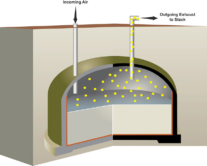
Active Headspace Ventilation
In an actively ventilated tank, outside air is drawn in from one tank riser (steel pipe) and exhausted out of a second riser. The incoming air mixes and dilutes headspace gases. Exhaust flows out through ductwork attached to the second riser and joins the exhaust from 3 to 7 other connected tanks. The exhaust from multiple tanks is piped to stacks that are 27 to 40 feet tall, where it is passed through a high-efficiency particulate (HEPA) filter to remove small particles and radioactive contaminants before it is dispersed into the atmosphere away from people.WRPS regularly monitors the composition of vapors coming from the tanks.
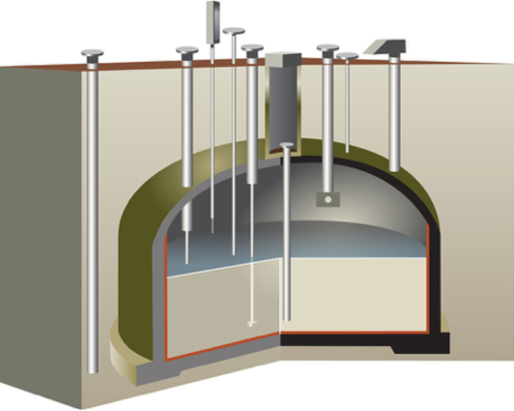
Passive Headspace Ventilation
The underground waste storage tanks have steel pipes (risers) that penetrate into the tank headspace. The risers are 4 to 42 inches in diameter and can extend from the tank headspaces to several feet above ground level. Most risers are covered; however, one riser is left opened and has a high-efficiency particulate air (HEPA) filter attached so that the tank can breathe with the outside air. This is necessary to prevent damage to the tank as outside air pressure changes with the weather. Headspace gases and vapors pass unimpeded through HEPAs filters which are designed to filter out small dust-like particles and radioactive contaminants.
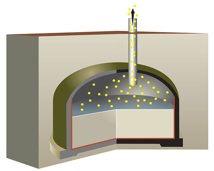
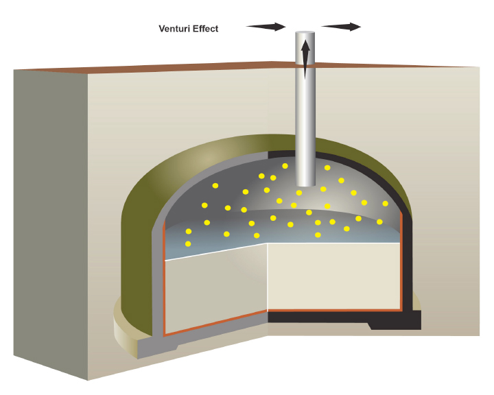
Barometric Breathing
Air exchange between a passively ventilated tank headspace and outside air is driven by the weather. As a result, ventilation rates change as the weather changes. Barometric pressure swings, cold ambient air temperatures, and wind provide driving forces that cause passive air exchange between the underground tanks and the outside air. When outside air pressure changes, this causes a small pressure imbalance between the headspace and outside air. This imbalance pushes air into the tank or draws it out (barometric breathing).

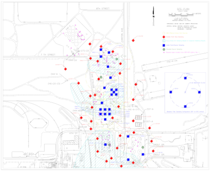
Atmospheric (Air) Dispersion Modeling & Sampling
Gas and vapor dispersion from passively and actively ventilated tanks is tracked through modeling, and by direct measurements in workplace using industry accepted sampling methods. The American Industrial Hygiene Association recommends that both be done to ensure worker protection.
Atmospheric (Air) dispersion models evaluate the effect of stack placement and height, terrain features like small hills and valleys, weather (temperature, wind speed, wind direction, humidity, etc.), and the effect from building structures. Pictured to the right is a plot showing modeled dispersion (light blue) and sampling locations. Read more.
PNNL-25654, Rev. 1, Atmospheric Dispersion Modeling Tools for Hanford Tank Farms Applications
Please follow the link above for a full synopsis and a link to the report.
PNNL-27530, Rev. 0, The APGEMS-TF Atmospheric Dispersion Model for Tank Farms Applications
In May of 2018, Pacific Northwest National Laboratory (PNNL) released the study, PNNL-27530, Rev. 0, The APGEMS-TF Atmospheric Dispersion Model for Tank Farms Applications.
The report describes the development and testing of the Air Pollutant Graphical Environmental Modeling System – Tank Farms (APGEMS - TF) software. Air Pollutant Graphical Environmental Modeling System (APGEMS) software was designed to simulate the dispersion of radiological particles at the Hanford site. The modified software, APGEMS-TF, was customized to address chemical vapor concerns in and around the Hanford tank farms. The ability to treat multiple simultaneous vapor emission points is a new feature of APGEMS-TF software. The locations for potential tank vapor emissions in the 200 East Area A Corridor and estimates of chemicals of potential concern (COPC) emission rates were built into the software. Several test cases were run with both single emission points and multiple emission points to demonstrate the capabilities and limitations of the APGEMS-TF version 1.0 model. PNNL scientists reported that the model is an appropriate tool for modeling chemical emissions within and around the tank farms, however, PNNL scientists also reported that the current model version predicts unrealistically large plumes in certain test cases. PNNL scientists are working to resolve these issues with the development of APGEMS version 1.1. Read more.